SUNTRIP AND ELECTRO-SOLAR VEHICLE
by Christophe Bayard, technical director.
Considering a long trip like the SunTrip in electro-solar vehicle requires a number of requirements to try to minimize the inconvenience inherent in such a journey. It is especially necessary to have tested the vehicle as much as possible before the trip so that the small “youth” failures have had time to declare themselves (and to be resolved). Then, once in the big bath, one is left to oneself and it is necessary to know a minimum the technical aspects of his vehicle in order to be able to be repaired if necessary. What a pity to be blocked with a broken down vehicle while the breakdown is perhaps minimal and easily repairable with the means at the hand.
Troubleshoot your vehicle requires 3 essential things:
-know how it works
-incognize what does not work anymore (diagnosis)
– have enough to repair or shunt what is down.
The mechanical aspects are often more obvious, especially for the novice, because they are “visible”. In addition, it is usually quite common to find local help for mechanical aspects.
Regarding the electrical aspects, it is often more difficult for the user because often the failure is not “visible”: nothing moves in the electrical aspect; and it is also more difficult to find local help.
So here is the time to look at the “noodle dish” of the electrical wiring of your vehicle to answer the first point: “know how it works.” Do not panic, nothing complicated but the knowledge of the system will begin by trying to have a global view of the operation and then to go into some details.
A electro-solar vehicle, how does it work?
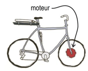
The motor can be in the hub of the front wheel, the rear wheel or the pedal. It is the motor that provides the power of assistance.
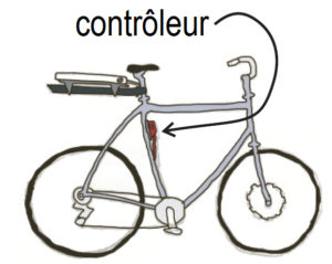
The motor controller is an electronic box that converts the power from the battery to deliver it to the engine according to a number of parameters such as the level of assistance, the speed of pedaling, the speed of the bike, the force of support on the pedals, etc. Each brand and controller manages differently the power transfer between the battery and the motor.
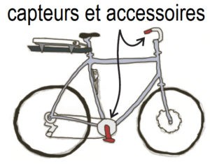
The motor controller needs sensors to know how to regulate power. The main ones are: the pedaling sensor (called P.A.S), the bike speed sensor, the assistance adjustment buttons and sometimes a manual control (throttle). Most Ebikes also have an indicator on the handlebars (and / or cycle-analyst) giving information on speed, level of assistance, battery level, etc…
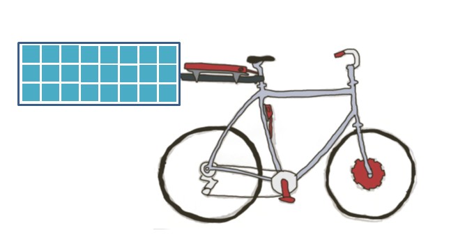
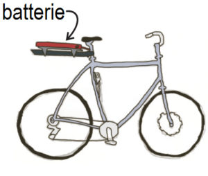
The battery is a key part of the power assistance. It’s the energy reservoir. It can be placed at different places on the vehicle. To recharge the battery, we use either a solar charger that draws its energy from photovoltaic panels or a charger plugged into a household power socket
All these elements are interconnected by electrical wiring. Electrical wiring is a fairly common source of failure. Indeed, a connector can be disconnected under the effect of vibration or when a cable was inadvertently pulled. Rainwater can get into the connectors and cause breakdowns. A cable can be pinched between 2 elements and cut or create a short circuit between 2 wires, etc.
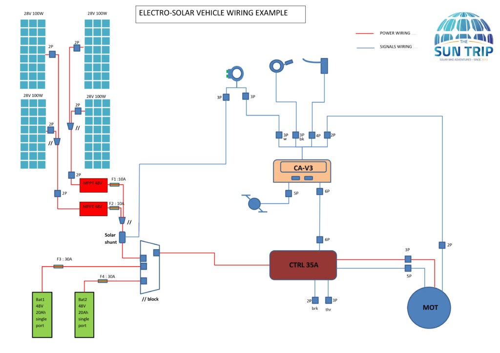
It is therefore very important to have a “state of play” of the wiring of your vehicle at the start in order to be able to intervene in case of failure. The inventory of equipment and wiring is materialized by an ELECTRICAL DIAGRAM.
I invite you to make an electrical diagram of the electrical equipment of your vehicle.
This diagram will be your best ally during a breakdown:
it allows to remember how the system works (we cannot remember everything)
it allows to check that everything is in conformity with the initial situation
it can be shared and understood by local help or remotely by phone
it allows to find solutions to modify the functioning to bypass the faulty equipments.
To make a diagram (see example below), it is necessary to follow the cables, wires and connectors between the different elements, to identify them and to represent them on the diagram. It takes a little time, but it will be a precious time to understand how it works.
What level of detail does it need? In most cases, the level of detail sufficient for simple troubleshooting is what is called a “single-line” pattern. This means that we only represent each cable that goes from one element to another or from one connector to another but without representing each wire inside the cable. However, it is advisable to distinguish between “power” cables (those that carry energy) and “control” cables (those that transmit only information). We can also indicate for each connector the type of connector or at least the number of pins and gender (male or female). If connectors are not connected to anything, however, they must be shown in the diagram to avoid the risk of creating an additional failure during trouble shooting by connecting something not planned to be connected. Fuses are very important elements that must be listed on the diagram indicating their size (in A). The more detailed the diagram, the more information it will give, but it will also be longer and more difficult to produce. A sketch in computer form is not essential. A diagram by hand drawing on a paper is enough if it is clear and well organized.
So now, sketch it! and see you all at the end of January for technical weekend talking about all this and many other things.
Christophe Bayard – Technical director (tech@thesuntrip.com)
